Model View Projection
In 3D engines, scenes are typically described as objects in three-dimensional space, with each object comprised of many three-dimensional vertices. Ultimately, these objects are rendered and displayed on a flat screen. Rendering a scene is always relative to the camera, and as such, the scene's vertices must also be defined relative to the camera's view.
When drawing a mesh in an OpenGL pipeline, a vertex shader will process every vertex, expecting the vertex's position to be defined in clip space. Model View Projection is a common series of matrix transformations that can be applied to a vertex defined in model space, transforming it into clip space, which can then be rasterized.
A vertex position is transformed by a model matrix, then a view matrix, followed by a projection matrix, hence the name Model View Projection, or MVP.
Model Space
Models, geometry and meshes are some series of vertices defined in model space. For example, a cube geometry could be defined as 8 vertices: , , , and so on. This would result in a 2x2x2 cube, centered at .
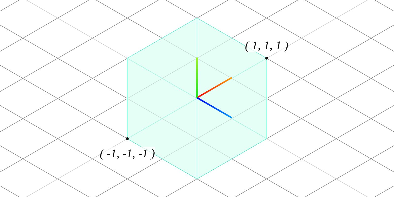
Often geometry is reused multiple times in the same render, at different locations or different sizes. Pushing unique vertices for each model instance is costly and unnecessary. A single set of geometry vertices can be shared across multiple instances, with each instance applying its own unique set of transformations, represented by a model matrix. The model matrix transforms vertices from model space to world space. A 2x2x2 cube centered at can be resized, twisted and placed anywhere when combined with a model matrix.
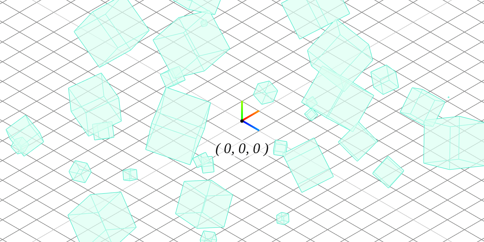
A model matrix is composed from an object's translation transform , rotation transform , and scale transform . Multiplying a vertex position by this model matrix transforms the vector into world space.
View
World space is the shared global 3D Cartesian coordinate system. Renderable objects, lights, and cameras all exist within this space, defined by their model matrix, all relative to the same point.
As all renders are from some camera's perspective, all vertices must be defined relatively to the camera.
Camera space is the coordinate system defined as the camera at , facing down its -Z axis. The camera also has a model matrix defining its position in world space. The inverse of the camera's model matrix is the view matrix, and it transforms vertices from world space to camera space, or view space.
Sometimes the view matrix and model matrix are premultiplied and stored as a model-view matrix. While each object has its own model matrix, the view matrix is shared by all objects in the scene, as they are all rendered from the same camera. Given a camera's model matrix , any vector can be transformed from model space, to world space, to camera space.
In an OpenGL system where the camera faces down -Z, any vertex that will be rendered must be in front of the camera, and in camera space, will have a negative Z value.
Projection
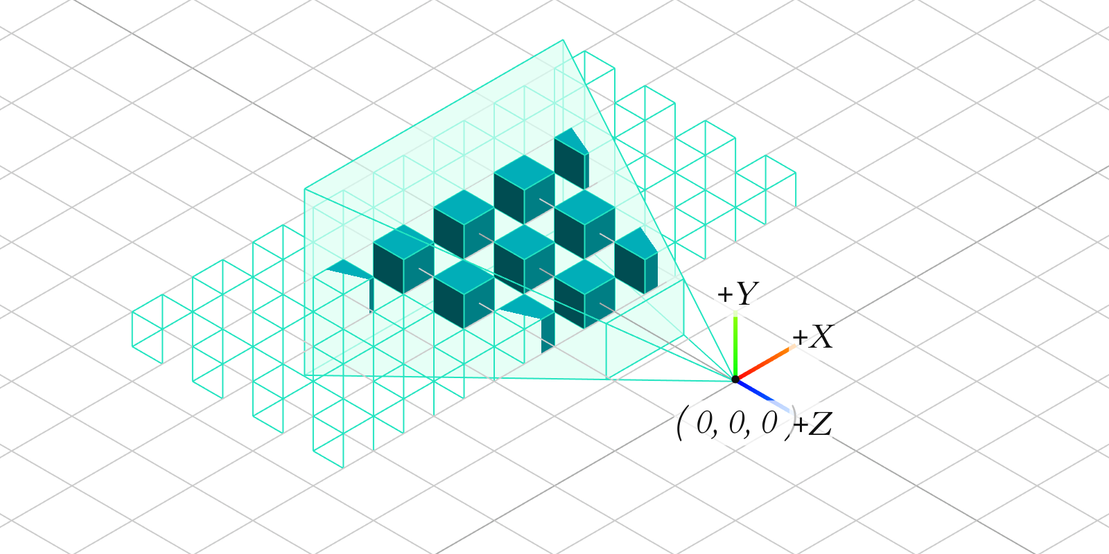
Once vertices are in camera space, they can finally be transformed into clip space by applying a projection transformation. The projection matrix encodes how much of the scene is captured in a render by defining the extents of the camera's view. The two most common types of projection are perspective and orthographic.
Perspective projection results in the natural effect of things appearing smaller the further away they are from the viewer. Orthographic projections do not have this feature, which can be useful for technical schematics or architectural blueprints for example. Much like how different lenses in a traditional camera can drastically change the field of view or distortion, the projection matrix transforms the scene in a similar way.
After applying a projection matrix, the scene's vertices are now in clip space. Note that the 3D vertices are represented by 4D vectors of homogeneous coordinates, with .
In camera space, after the model-view transformations, is still unchanged and equal to 1. However, perspective projection is a large reason the 4th coordinate is needed, and may no longer equal 1 after applying projection.
The vertex shader in OpenGL expects vec4 gl_Position to be set to clip space coordinates. Once the vertex shader finishes and the clip space position is known, the pipeline automatically performs perspective division, dividing the components by the value turning the 4D vector back into a 3D vector, resulting in the vertex finally being in normalized device coordinates.
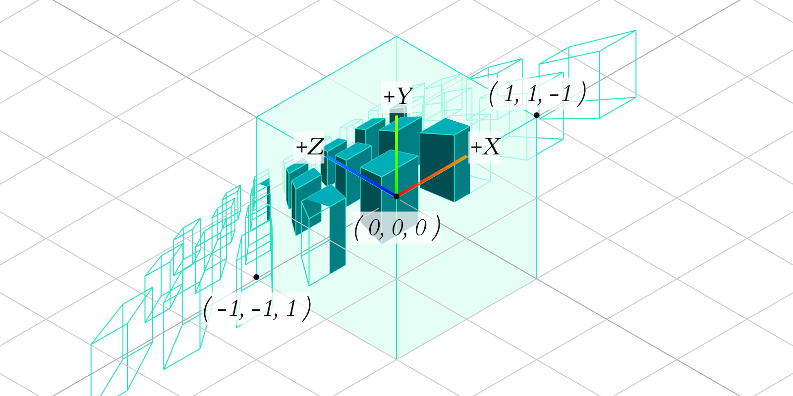
At this point, the pipeline discards any vertices outside of a 2x2x2 cube with extents at and . The entire visible scene, defined by the projection matrix, is now collapsed into a cube, with frustum extents defining how much was squashed into that cube, with the near plane mapped to and the far plane mapped to .
The model, view, and projection matrices transform vertices that start in model space, and then world space, camera space, and then clip space. The vertices are then transformed into normalized device coordinates via implicit perspective division. Finally, during rasterization, a viewport transform is applied to interpolated vertex positions, resulting in a window space position: an X and Y position of a texel in two dimensions, translating some point in 3D space relative to some viewer, into a specific pixel on a screen.
